Plc-5 Devicenet Scanner Module User Manual
Publication 1771-IN014B-EN-P - September 2001
20 DeviceNet Scanner Module Catalog Number 1771-SDN/C
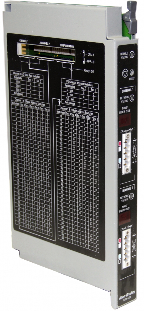
Oct 14, 2019 Allen-Bradley 1771-SDN 2-Channel DeviceNet Scanner Module acts as an interface between DeviceNet devices and a PLC-5 processor providing 9092.
- The Allen Bradley 1794-ADN is a DeviceNet Scanner Interface Module which interfaces FLEX I/O modules to an I/O scanner port across the DeviceNet network. The Interface Module features a built-in 24V DC power supply and can interface with upto 8 I/O Modules. This unit does not feature the conformal coating and can therefore not be used in toxis enviroments.
- 1771-SDN PLC DeviceNet Scanner Module The 1771-SDN/C DeviceNet Scanner Module works with both Series A/B. Series C is an option as a spare or replacement with one consideration that you change the Switch to off or “0” position in the Configuration switchbank as shown below.
- The 1771-SDN is a DeviceNet scanner module that belongs to the 1771 series of I/O modules and it is manufactured by Allen-Bradley. The main function of this module is to allow data exchange between the PLC processor and the DeviceNet devices.
The following table outlines the module command register’s bit
numbers and descriptions.
Module Command Register - Word 0, Block 62
Bit
Number
Bits
Operating Mode
Operating Mode Description
01
00
00 – 01
0
0
DeviceNet Channel 1
in idle mode
Idle
The scanner does not map output data to the devices, but keeps network
connections to devices open so device failures can be detected. Input data
is returned from devices, and mapped into the scanner input table and the
discrete inputs. Outputs on the network are not under program control and
will be in their configured ‘idle state.’ The scanner must be put into this
mode to perform configuration of the scanner database tables.
Run
The scanner module maps output data from its scanner output table and
discrete outputs to each device on the network. Inputs are received and
mapped into the scanner input table and discrete inputs. Outputs on the
network are under program control.
Placing the PLC-5 into PROG or REM_PROG mode places the scanner into
idle mode regardless of the state of the bits in the module command
register. Placing the PLC-5 into RUN or REM_RUN mode causes the state
of the bits in the module command register to determine the scanner state.
Fault Network
The scanner stops communicating with devices on the network. No
outputs or inputs are mapped. Outputs on the network are not under
program control. If the scanner was in run, devices will go to their
configured ‘fault state.’
Enable
The DeviceNet channel is enabled for communication. This is the normal
operating state of the channel.
Disable
The DeviceNet channel is disabled for communication. No communication
may occur over this channel. Outputs on the network are not under
program control. If the scanner was in run, devices will go to their
configured ‘fault state.’ Numeric error code 90 will occur when channel is
disabled.

Scanner Active
This is the normal operating mode of the scanner.
Scanner Halt
All scanner operations stop when this command is issued. No
communications occur over either DeviceNet port. No block transfer or
discrete I/O mapping occurs. Outputs on the network are not under
program control. If the scanner was in run, devices will go to their
configured ‘fault state.’ Numeric error code 97 will occur - you must reset
the scanner or cycle power to the scanner to recover from this state.
Scanner Reboot
This command causes the scanner to reset as though the reset button had
been pressed. When this command is issued, all scanner communication
stops for the duration of the scanner’s initialization sequence. Outputs on
the network are no longer under program control. If the scanner was in
run, devices will go to their configured ‘fault state.’
0
1
DeviceNet Channel 1
in run mode
1
0
DeviceNet Channel 1
in fault mode
1
1
Reserved
02 - 03
0
0
DeviceNet Channel 2
in idle mode
0
1
DeviceNet Channel 2
in run mode
1
0
DeviceNet Channel 2
in fault mode
1
1
Plc 5 Manual
Reserved
04
0
Enable DeviceNet
Channel 1
1
Disable DeviceNet
Channel 1
Plc 5 Devicenet Scanner
05
0
Enable DeviceNet
Channel 2
Plc 5 Programming Manual
1
Disable DeviceNet
Channel 2 Oceanic atom 2.0 user manual.
Plc 5 User Manual
06
0
Scanner run
1
Scanner halt
07
0
Scanner Active
1
Scanner reboot

08 – 15
0
Reserved for future use